
The Ultimate Guide to Managing Thermal Distortion in CNC Laser and Plasma Cutting: DXF Design and Heat Dissipation Techniques

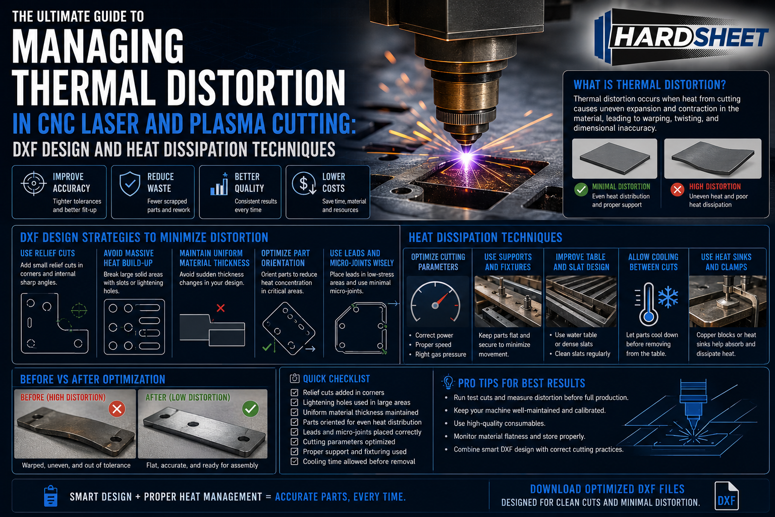
In precision CNC sheet metal fabrication, controlling dimensional accuracy is not just about choosing the correct feed rates or calibrating the focal position of your machine. One of the most destructive variables on the factory floor is thermal distortion (thermal warping/ısıl çarpılma).
When a high-power 12kW fiber laser beam or a concentrated CNC plasma arc strikes a raw steel sheet, it introduces localized heat exceeding several thousand degrees Celsius. As the cutting torch moves along its path, this extreme heat creates a highly uneven temperature gradient across the metal plate. The zone immediately surrounding the cut expands rapidly, while the surrounding cold material resists this movement.
The structural result? Internal residual stresses build up, causing the sheet metal to buckle, warp, bow, or lift off the cutting bed support slats. In worst-case scenarios, a warped part can tip upward, causing the high-speed CNC cutting head to crash directly into the component, damaging fragile optics or throwing the axis motors completely out of alignment.
To run a highly profitable and automated fabrication shop, you cannot simply cross your fingers and hope the sheet stays flat. You must actively manage heat dissipation. This comprehensive, 1000+ word engineering guide will break down the mechanics of thermal expansion and analyze the advanced CAD drawing strategies and nesting workflows required to eliminate heat warping.
1. The Physics of Thermal Expansion in Sheet Metal
To mitigate thermal deformation, engineers must first analyze how different metals react to localized thermal cycles. The susceptibility of a sheet metal component to distortion is governed primarily by three physical properties:
-
Coefficient of Thermal Expansion (CTE): This metric defines how much a material expands per degree of temperature change. For example, Austenitic Stainless Steel (304/316 Grades) has a CTE roughly 1.5 times higher than standard Carbon/Mild Steel. This explains why stainless steel projects warp significantly faster under a laser path.
-
Thermal Conductivity: This represents the speed at which a material transfers heat away from the cutting zone. Aluminum has exceptionally high thermal conductivity; it disperses heat across the entire sheet rapidly, reducing local hot spots. Mild steel, having lower conductivity, traps heat right at the cutting edge, intensifying local expansion.
-
Material Thickness: Thin sheets ($0.5\text{mm}$ to $2.0\text{mm}$) lack the structural mass to resist bending forces, warping instantly under heat. Thick plates ($6\text{mm}$ and above) possess high structural rigidity but accumulate massive internal residual stresses that can cause sudden, violent jumping during stress relief cuts.
Plaintext
 HIGH LOCAL HEAT (No Dissipation)           OPTIMIZED HEAT PATH (Hardsheet Standard)
     ┌────────────────────────┐                 ┌────────────────────────┐
     │   🔥 HOT ZONE          │                 │ ➔  ➔ HEAT FLOW ➔ ➔    │
     │ (Trapped Heat Warps)   │                 │ (Relief Slots/Bridges) │
     └────────────────────────┘                 └────────────────────────┘
    (Causes Metal to Buckle)                     (Preserves Flat Geometry)
2. DXF CAD Engineering Strategies to Dissipate Heat
The most effective way to eliminate thermal distortion is to address it during the 3D modeling and 2D DXF optimization phase, long before the file ever reaches the CNC machine computer. Professional technical draughtsmen implement specific structural geometries to manage the thermal footprint.
Technique 1: Implementing Thermal Relief Slots (Isı Dağıtma Kanalları)
If a DXF design involves long, continuous parallel cut lines (such as the outer structural walls of flat-pack grills or industrial shelving), the heat accumulates linearly along that edge.
-
The Engineering Fix: By introducing alternating, stitched micro-joints or integrated thermal relief slots, you break up the linear continuity of the heat path. These slots act as expansion barriers, allowing localized sections of the metal to expand independently into open air gaps without buckling the main structural body of the part.
Technique 2: Stitch and Tab Geometry for Interlocking Frameworks
When designing interlocking modular assemblies like parametric metal furniture or heavy-duty fire pits, parts must fit together with tight mechanical tolerances.
-
The Engineering Fix: Instead of designing solid, unbroken internal cutout windows, utilize a series of structural bridge tabs. Leaving precise material bridges keeps the surrounding skeleton matrix rigid, forcing the sheet metal to remain flat during the intense cutting cycles.
Technique 3: Corner Radii and Stress-Relief Loops
Sharp, angular corners act as severe thermal traps. When a laser or plasma head enters a sharp 90-degree internal angle, the CNC gantry must decelerate to change direction. During this split second of deceleration, the cutting torch continues to emit full power, dumping an enormous spike of heat into a single point.
-
The Engineering Fix: Replacing sharp internal vertex points with clean mathematical corner radii or stress-relief loops keeps the machine moving at a uniform feed rate, ensuring consistent thermal dispersion along the path.
3. CAM and Nesting Workflow Optimizations
Once your DXF vectors are structurally optimized for heat management, the nesting software operator must apply the correct toolpath sequencing to distribute the thermal load across the physical layout.
Plaintext
  POOR SEQUENCING (Linear Concentration)    OPTIMIZED SEQUENCING (Distributed Heat)
 ┌──────────────────────────────────────┐  ┌──────────────────────────────────────┐
 │  [1] ───► [2] ───► [3] ───► [4]      │  │  [1] ───► [3] ───► [2] ───► [4]      │
 │  (Overheats Left Side of Sheet)      │  │  (Alternating Paths Balance Heat)    │
 └──────────────────────────────────────┘  └──────────────────────────────────────┘
Strategy 1: The Leap-Frog / Distributed Cutting Method
Never program your CNC machine to cut adjacent parts sequentially down a single row. Concentrating the toolpath in one small quadrant will quickly overheat that section of the sheet, causing massive localized bowing.
-
The Solution: Configure your CAM software (such as CypCut or TruTops) to use a distributed cut sequence. Program the torch to cut a part on the far left, leap-frog to the far right, move to the center, and loop back. This gives previously heated zones precious time to cool down.
Strategy 2: Internal Profiles First
Always cut internal holes, decorative slits, and nested sub-components before cutting the outer perimeter profile of a part. If you cut the outer perimeter first, the part detaches from the main rigid sheet framework. Cutting internal details on a detached, floating part means the component lacks structural support and will warp or shift instantly due to thermal movement.
Conclusion: Engineered Vectors Mean Flawless Production Runs
In high-volume manufacturing, a sheet metal part that deforms during production is a multi-layered loss. It wastes expensive raw materials, burns valuable machine time, ruins cutting consumables, and compromises the tight dimensional tolerances required for modern press brake bending and assembly.
At Hardsheet, we believe that an exceptional DXF blueprint must anticipate the physical and thermal laws of the factory floor. We do not simply trace silhouettes; we engineer thermal and mechanical integrity into every line. Every digital template in our commercial catalog is designed by an experienced technical draughtsman who understands heat dissipation paths, gantry deceleration limits, and structural stress zones.
Our files incorporate precise node optimization, smooth arc transitions, and calculated structural reliefs that prevent torch pausing and heat accumulation. When you build with a Hardsheet blueprint, your CNC machine runs faster, your cutting head remains safe from crashes, and your finished parts drop off the table perfectly flat.
Control the heat. Eliminate manufacturing scrap. Choose engineered precision.
👉 [Browse Our Full Catalog of Heat-Optimized, Precision DXF Blueprints] (Not: Buraya site linkini ekle)



Merely wanna comment on few general things, The website layout is perfect, the subject matter is really superb : D.