The Engineer’s Guide to Designing CNC Van Conversion Panels: CAD Workflows and 2D DXF Templates for Ford Transit & Custom


The global rise of the mobile living movement, fleet customization, and overland van conversions has transformed vehicle interior lining into a highly profitable sector for CNC routing and laser cutting workshops. Both professional conversion firms and DIY builders are moving away from manually tracing cardboard templates on garage floors. Instead, the modern industry demands precision-engineered, digital 2D DXF templates that can be loaded straight into a CNC machine for instant production.
However, translating the complex, multi-radiused internal skeleton of a commercial vehicle like the Ford Transit or Ford Transit Custom into a flat, production-ready vector file is an extraordinary design challenge. Vehicles are not square boxes. The structural pillars taper inward toward the roof, the chassis contours feature complex mechanical indentations, and factory rivet holes require absolute positional placement.
If your DXF wall panel templates fail to account for structural curvature, localized sheet metal tolerances, or toolpath corner compensation, the panels will buckle, rattle, or require hours of manual trimming during installation.
This comprehensive, 1000+ word engineering guide breaks down the precise CAD design workflows, hardware clearance rules, and CNC nesting strategies required to manufacture flawless van interior wall lining panels and flooring kits.
1. The Geometry of a Commercial Van Fleet: Transit vs. Custom
Before initializing a CAD sketch, a technical draughtsman must distinguish between the structural architectures of different commercial vehicle classes. While they share the same brand heritage, the Ford Transit (Full-Size) and Ford Transit Custom (Mid-Size) require entirely separate geometric baseline frames.
-
The Ford Transit (Full-Size Cargo Van): Designed for maximum payload volumes, the vertical wall pillars stretch significantly higher before tapering inward. Because these vehicles are frequently subjected to intense structural flexing under heavy rear axle loads, the internal 2D panels must feature minor elastic gap tolerances ($2.0\text{mm}$ to $3.0\text{mm}$ expansion clearances) along major horizontal floor-to-wall junctions to prevent panel bowing over time.
-
The Ford Transit Custom (Mid-Size Van): Featuring a much more aerodynamic, passenger-car-like profile, the side walls curve sharply inward from the mid-belt line upward. This dramatic curvature demands highly flexible, lightweight materials (such as $4.0\text{mm}$ plywood or structural composite sheets) and meticulously calculated rivet hole centers along the curved wheel-well arches and window contours.
Plaintext
       FORD TRANSIT (Full-Size)                FORD TRANSIT CUSTOM (Mid-Size)
         ┌──────────────────┐                      ┌──────────────────┐
         │                  │                      │   /          \   │  ◄── Sharp Upper
         │                  │                      │  /            \  │      Taper
         │                  │                      │ │              │ │
         └──────────────────┘                      └──────────────────┘
     (Straight, Tall Wall Profiles)               (Pronounced Aerodynamic Curve)
2. Material Selection and CNC Machining Parameters
The material type selected for the interior lining kit dictates how the 2D DXF vectors must be handled during the CAM toolpath programming phase.
Premium Lightweight Plywood (Poplar / Birch / Ceiba)
-
Recommended Thickness: $4.0\text{mm} – 6.0\text{mm}$ for wall and ceiling panels; $9.0\text{mm} – 12.0\text{mm}$ for heavy-duty sub-floors.
-
CNC Router Tooling Setup: When machining plywood kits on a CNC router table, always select a down-cut spiral carbide compression bit. A down-cut tool forces the wood fibers downward against the vacuum table, entirely preventing splintering or tearing along the top veneer surface, ensuring clean, paint-ready or fabric-wrap edges right off the machine bed.
Aluminum Composite Panels (ACP / Dibond)
-
Recommended Thickness: $3.0\text{mm} – 4.0\text{mm}$ consisting of dual aluminum skins bonded to a polyethylene core.
-
CNC Processing Setup: ACP offers exceptional structural rigidity, moisture resistance, and extreme weight savings for high-end conversion modules. It can be effortlessly sliced on a CNC router or a fiber laser table using matching aluminum cutting gas parameters.
3. Critical CAD Design Rules for Precision Wall Lining Kits
To design a high-quality van wall panel DXF kit that earns industry authority, your vector paths must integrate several specialized technical allowances:
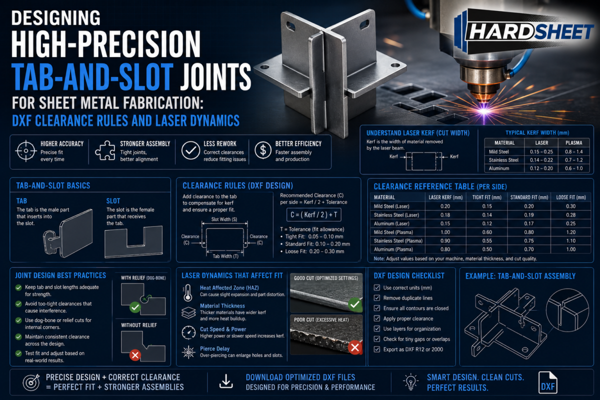
Rule 1: The “Dog-Bone” Corner Compensation for CNC Routers
Unlike a laser beam, a mechanical CNC router spindle uses a spinning cylindrical tool bit (e.g., a $6.0\text{mm}$ or $1/4\text{inch}$ endmill). Because the cutter is round, it cannot cut a sharp internal $90^\circ$ corner inside locking panel tabs or recess pockets for factory cargo tie-down rings.
-
The Engineering Fix: Always implement dog-bone or T-bone fillets at the internal corners of structural pocket contours. This allows the routing bit to extend slightly past the true vertex, clearing out the wood mass so structural clips or tie-down hardware fit perfectly flush against the sheet metal skeleton.
Rule 2: The Scribe/Trim Margin Allocation
Commercial van bodies shift slightly during manufacturing assembly line production; two identical model-year Transits can exhibit variance up to $4.0\text{mm}$ in rear pillar spacing.
-
The Engineering Fix: A professional DXF layout does not draw panels to hit the absolute dead-end perimeter of the steel skin. Always design a subtle $3.0\text{mm}$ perimeter clearance buffer along the extreme vertical bulkheads. For custom cabinet faces or partition walls, incorporate an optional $15\text{mm}$ “scribe margin” that a professional upfitter can quickly sand down to match modified insulation profiles.
Rule 3: Factory Rivet Hole Center Mapping
The factory wall frames of Ford commercial vans feature pre-punched hexagonal and circular mounting holes designed for plastic expanding push-pins or M6 rivnuts.
-
The Engineering Fix: Your 2D DXF templates should separate the cut lines into distinct vector layers. Layer 1 should map the true outer panel perimeter. Layer 2 must pinpoint the exact center locations of these factory mounting positions, using a standard diameter array ($6.5\text{mm}$ or $9.0\text{mm}$ depending on the fastener strategy). This completely removes the tedious task of drilling into the vehicle’s structural steel skin during assembly.
Plaintext
      [LAYER 1: OUTER BOUNDARY]  ──►  Continuous Vector Outer Path
      [LAYER 2: MOUNTING CENTERS] ──►  Precision $6.5\text{mm}$ Circular Hole Array
4. Maximizing Yield: Advanced Nesting for Sheet Materials
Van wall panels are naturally large, sweeping geometric silhouettes that can quickly create massive industrial material waste if nested poorly across a standard $2500\times1250\text{mm}$ ($8\times4\text{ft}$) or $3000\times1500\text{mm}$ industrial sheet array.
-
Common Nesting Layouts: By carefully mirroring and interlocking the left-side and right-side rear quarter panels across a single layout bed, you can drastically minimize scrap metal or plywood waste.
-
Small Component Recovery: Utilize the open interior cutout windows (the zones where the vehicle’s structural windows would be placed) to nest smaller secondary components, such as wiring loom access covers, wheel arch housing brackets, or custom electrical switchboard plates. This optimization significantly drives down overall material cost per van kit.
Conclusion: Engineered Templates Streamline Vehicle Conversions
In the high-growth commercial van upfitting marketplace, efficiency dictates profitability. A precision-engineered 2D DXF template transforms an expensive, multi-day hand-fitting modification into a rapid, highly automated assembly sequence.
At Hardsheet, we treat van lining geometry with strict engineering absolute metrics. We don’t supply loosely traced vector sketches. Every digital template in our specialized automotive conversion catalog is developed by drawing from detailed 3D chassis scans, factory skeleton coordinates, and advanced CNC machining tolerances.
Our templates incorporate exact factory rivet hole alignment layers, calculated router bit path reliefs, and dynamic curvature profiles that eliminate panel stress and buckling. When your workshop loads a Hardsheet blueprint, the finished panels drop straight onto the van skeleton, lining up seamlessly with the vehicle’s structural pillars from the very first press of the push-pins.
Accelerate your conversion times. Eliminate material waste. Build with engineered precision.
👉 [Access Our Production-Ready Library of Precision Van Conversion DXF Templates]