
Designing High-Precision Tab-and-Slot Joints for Sheet Metal Fabrication: DXF Clearance Rules and Laser Dynamics


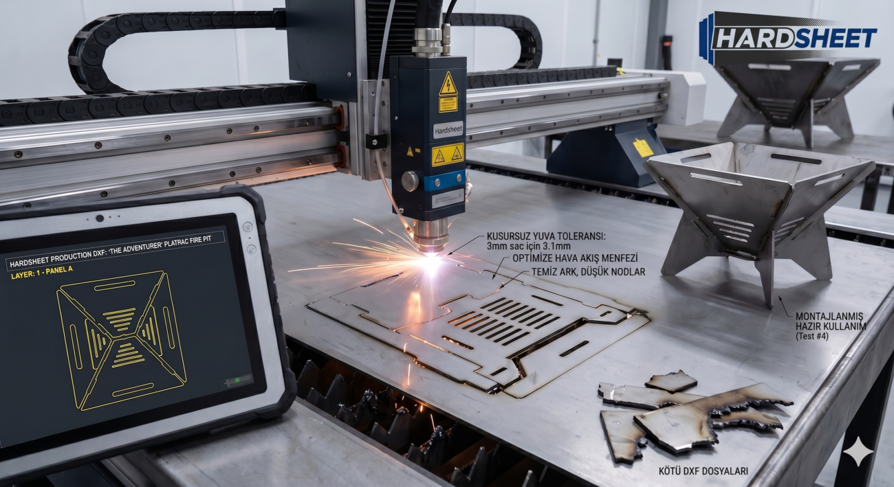
In precision CNC sheet metal manufacturing, minimizing production costs is directly tied to eliminating manual labor downstream. Traditional fabrication workflows often require a welder to spend hours clamp-fixturing flat-cut components together, verifying dimensions with a square, and grinding down excess weld beads before powder coating.
To overcome this operational bottleneck, modern industrial draft designs rely heavily on Tab-and-Slot (Interlocking/Geçme ve Sekme) mechanics.
When a 2D DXF blueprint features engineered tabs and matching slot entries, the components align and self-fixture mechanically during assembly. This completely eliminates the need for expensive welding jigs, prevents human alignment errors, and cuts post-processing times by up to 70%.
However, designing a functional tab-and-slot joinery array is not as simple as drawing identical rectangles on a screen. If your clearance tolerances do not account for laser beam width (kerf), material thickness deviations, or corner micro-fillets, the parts will either refuse to fit together on the shop floor or fit too loosely, compromising structural integrity.
This comprehensive, 1000+ word technical guide will break down the exact mathematics and engineering principles required to design production-ready interlocking sheet metal joints.
1. The Physics of Interlocking Joints: Kerf and Material Gauges
To calculate the exact spatial boundaries of your tabs and slots within a 2D vector graphic, you must understand how a CNC fiber laser or plasma cutter interacts with raw steel plate.
The Laser Kerf Factor
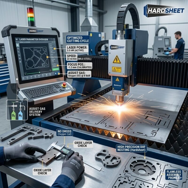
Every cutting torch carries a physical footprint known as the kerf—the width of material melted away by the focused beam. A standard high-power fiber laser cutting a $2.0\text{mm}$ mild steel plate typically exhibits a kerf width between $0.15\text{mm}$ and $0.25\text{mm}$.
-
The Structural Result: If you design a tab that is exactly $10.0\text{mm}$ wide and a slot that is exactly $10.0\text{mm}$ wide inside your CAD sketch, the laser will cut the tab slightly smaller (approx. $9.8\text{mm}$) and burn the slot slightly larger (approx. $10.2\text{mm}$). While a basic loose fit is acceptable for ornamental frames, it creates critical structural failures in heavy-duty structural shelving or parametric furniture.
Mill Tolerances and Thickness Variances
Raw sheet metal coils straight from the steel mill are never perfectly uniform. A commercial sheet marked as nominal $3.0\text{mm}$ Hot Rolled steel can dynamically vary from $2.85\text{mm}$ to $3.15\text{mm}$ across its surface profile. If your slot depth or slot width is designed too tightly, a sheet at the higher end of the mill tolerance scale will fail to slide into position, forcing the operator to grind individual tabs down manually.
Plaintext
  INCORRECT (Sharp Corner Binding)            CORRECT (Engineered Relief Cuts)
     ┌───────────┐   ┌───────────┐               ┌───────────┐   ┌───────────┐
     │           └───┘           │               │   (○) ┌───┘   └───┐ (○)   │ ◄── Relief Holes
     │   BINDING CORNER          │               │       │           │       │
     └───────────────────────────┘               └───────┴───────────┴───────┘
  (Parts Jam Due to Laser Radius)                  (Flawless Flush Fit)
2. Setting the Universal Clearance Formula for DXF Layouts
To establish the perfect engineering balance between an effortless mechanical slip-fit and high structural rigidity, your CAD architecture must apply precise clearance scaling variables ($C$).
The Slot Width Formula (The Material Entry Dimension)
The length of the slot entry dictates how easily a tab inserts vertically. The formula for the total slot length ($S_L$) relative to the tab length ($T_L$) is calculated as follows:
$$S_L = T_L + 2 \cdot C$$
Where $C$ represents the custom clearance modifier based on material thickness and cutting method.
The Slot Height Formula (The Thickness Dimension)
The thickness entry parameter of the slot ($S_H$) must absorb both mill thickness tolerances and laser height variations:
$$S_H = T_{\text{nominal}} + C$$
Standard Engineering Clearance Matrix for CNC Laser:
-
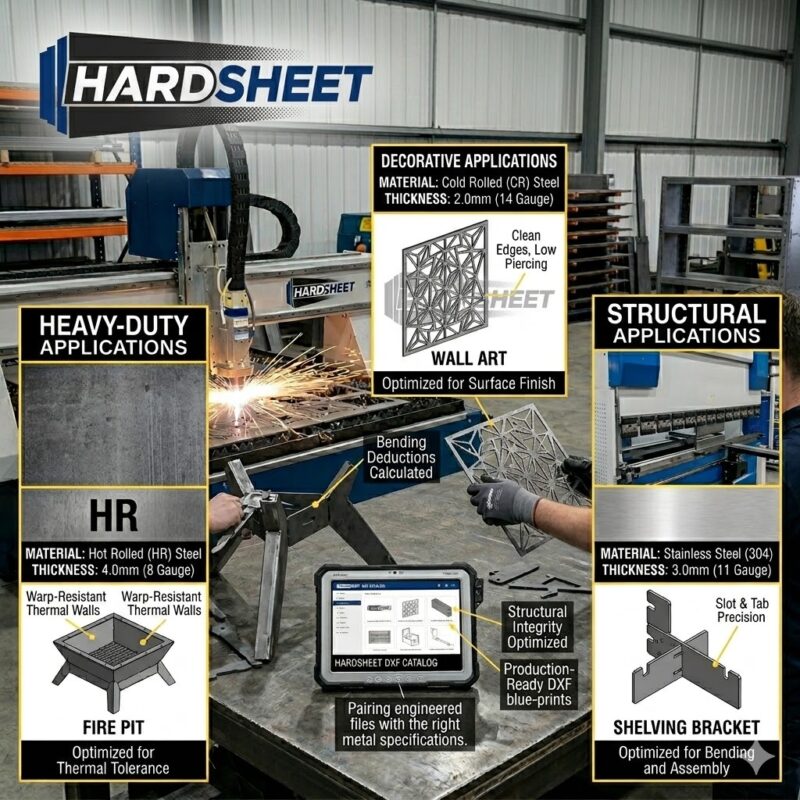
Thin Sheets ($1.0\text{mm} – 2.0\text{mm}$): Apply a global clearance factor of $C = 0.05\text{mm}$ to $0.10\text{mm}$. This generates a crisp, highly professional friction-fit ideal for decorative wall arts, consumer electronics enclosures, and heavy-duty laptop stands.
-
Medium Plates ($3.0\text{mm} – 5\text{mm}$): Apply a clearance factor of $C = 0.15\text{mm}$ to $0.20\text{mm}$. This ensures that heavy structural parts, flat-pack fire pits, and grills slide together smoothly even if the plates carry slight surface mill scale or oil films.
-
Heavy Fabrication (Above $6\text{mm}$): Increase the clearance parameter to $C = 0.25\text{mm}$ to $0.30\text{mm}$ to compensate for the wider kerf profiles of high-amperage plasma or thick-beam oxygen laser cutting.
3. Solving the Corner Radius Problem: Dog-Bones and T-Bone Reliefs
When a laser cutting head approaches an internal corner inside a slot geometry, it cannot generate an absolute, perfectly sharp $90^\circ$ angle. Because the laser beam profile is circular, every internal corner carries a tiny, unavoidable material radius equal to half the kerf width.
When a sharp-edged tab attempts to slide into a slot with a slightly radiused internal corner, the vertex points bind against each other. The tab jams halfway through the slot, failing to mount flush.
The Engineering Solution: Relief Node Cutouts
To guarantee a flush structural connection, professional draft layouts implement geometric relief cuts at the root vertex points of the slots.
-
The Dog-Bone Relief: Tiny circular arc cutouts are placed symmetrically at both internal corners of the slot. This pushes the laser path slightly outward past the nominal boundary, clearing out the extra material corner mass so the square tab edge can seat completely flat.
-
The T-Bone Relief: A single vertical relief path is extended straight down past the slot boundary. This is highly efficient for automated CAM processing, allowing the laser to maintain velocity while ensuring perfect clearance for mating sheets.
4. Advanced Structural Rules for High-Volume Interlocking Runs
When designing a complex 3D assembly intended for automated commercial nesting, your tab-and-slot layouts must respect these four structural rules:
-
Rule 1: Tab Aspect Ratio: Never draw tabs that are exceptionally long and skinny, as they will buckle under load. The length of a tab ($T_L$) should ideally be configured between $4 \times \text{Material Thickness}$ and $8 \times \text{Material Thickness}$.
-
Rule 2: Tab Pitch (Spacing): To prevent localized plate bowing along long sheet junctions, space your tabs uniformly. The ideal distance between interlocking tabs should equal $15 \times \text{Material Thickness}$ to $25 \times \text{Material Thickness}$.
-
Rule 3: Wedge/Pin Integration: For 100% glue-free and weld-free flat-pack assemblies (like tactical shop furniture or overland camp stoves), cut a secondary rectangular hole through the protruding tip of the tab. This allows a tapered metal wedge or pin to be hammered in, locking the entire 3D frame together under permanent mechanical tension.
Conclusion: Engineering the Future of Self-Fixturing Manufacturing
In a modern manufacturing ecosystem, reducing machine cycle time means nothing if your structural components stall on the assembly floor due to manual fitment adjustments. A precision-engineered 2D DXF vector layout must bridge the gap between abstract computer software architecture and the gritty mechanical realities of thermal heat, laser kerf, and metallurgy.
At Hardsheet, we transform standard 2D vector drawing arrays into highly optimized industrial blueprints. Every digital template in our commercial catalog is developed by an experienced technical draughtsman who calculates exact bending allowances, corner micro-relief paths, and precise tab-and-slot friction tolerances.
Our designs fit together perfectly right off the cutting bed with zero hammer forcing or grinding required. We minimize your shop floor overhead, completely isolate human errors, and streamline your production flow from the very first strike of the laser torch.
Optimize your fabrication efficiency. Eliminate manual grinding hours. Build with engineered precision.
👉 [Explore Our Full Catalog of Interlocking, Precision Tab-and-Slot DXF Templates]



I have read some good stuff here. Certainly worth bookmarking for revisiting. I wonder how much effort you put to make such a fantastic informative web site.