
How to Eliminate Dross in CNC Plasma Cutting: Machine Tuning & DXF Optimization

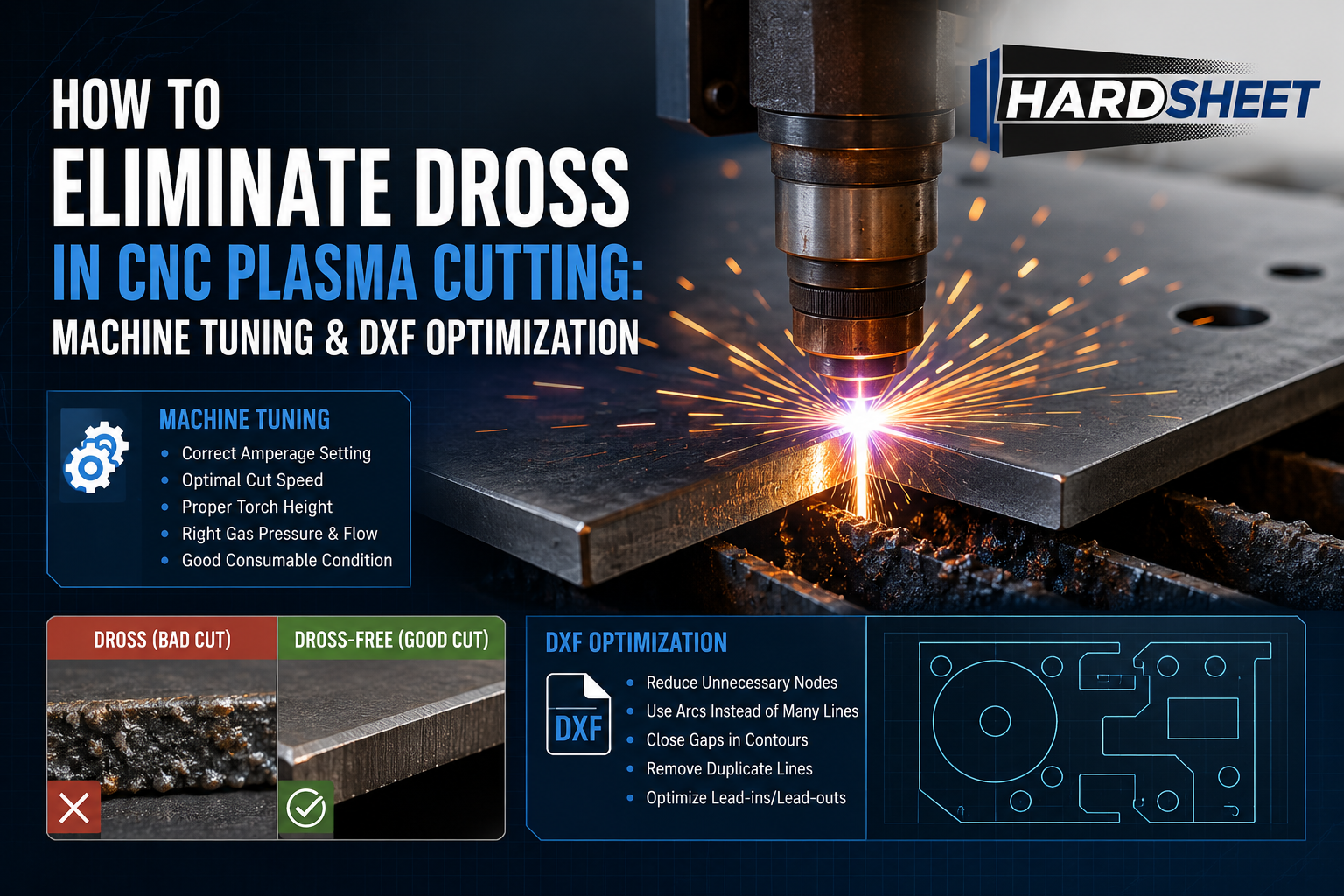
Every CNC plasma operator knows the frustration of lifting a freshly cut steel sheet off the water table, only to find the back of the parts covered in thick, rock-hard slag. Cleaning dross (burr/çapak) manually with a chipping hammer or grinder wastes valuable shop hours and ruins your post-processing efficiency.
While dross is often treated as a strictly mechanical issue (like incorrect speed or worn consumables), the truth is that poorly optimized DXF files are just as responsible for heavy slag buildup.
In this industrial guide, we’ll explore both the machine tuning parameters and the hidden CAD drawing techniques required to achieve clean, dross-free plasma cuts.
1. High-Speed Dross vs. Low-Speed Dross
Before turning any dials, you need to look at the slag. The shape and hardness of the dross tell you exactly what your plasma torch is doing wrong:
-
Low-Speed Dross: If the slag forms thick, bubbly, and glob-like structures that are incredibly easy to knock off with a chisel, your torch is moving too slowly. The plasma arc is staying in one place too long, melting more metal than the air pressure can blow away.
-
High-Speed Dross: If the slag forms a thin, sharp, hard bead right along the bottom edge that feels welded to the metal, your torch is moving too fast. The arc is lagging behind the torch head, failing to blow the molten metal out cleanly.
2. Torch Height Control (THC) and Voltage Calibration
Plasma cutting relies heavily on maintaining a precise distance between the nozzle and the metal plate (arc voltage).
If your Torch Height Control (THC) is improperly calibrated, or if your DXF file has overlapping lines that cause the torch to pause, the voltage will spike. The torch will suddenly dive or rise, instantly altering the cut width (kerf) and leaving heavy dross on the underside of your sheet metal.
3. The Corner Slowdown Problem (Where CAD Meets Machine)
When a CNC plasma machine reaches a sharp 90-degree corner, the gantry mechanical components must decelerate to change direction.
-
The Slag Build-Up: Because the machine slows down at the corner, the plasma arc spends too much time on that single point, causing massive heat buildup. This leads to blown-out corners and heavy low-speed dross.
-
The DXF Engineering Fix: Professional technical draughtsmen don’t leave sharp, dead-end internal corners in heavy-duty DXF templates. By implementing subtle corner loops, external radii, or smooth arc transitions, we allow the CNC controller to maintain a steady feed rate throughout the entire geometry, preventing the torch from pausing and burning the metal.
4. Lead-In Geometry and Piercing Height
If a plasma torch pierces directly on the cutting path, the molten blowout will ruin the edge quality and create a permanent crater of dross.
An engineered DXF file must allow enough clearance for curved or angled lead-ins. This ensures that the torch pierces the metal in a “scrap” zone, stabilizes its arc voltage, and enters the actual part geometry smoothly at full cutting speed.
Conclusion: Cut Clean, Save Grinding Hours
Minimizing post-processing time is the secret to running a highly profitable CNC fabrication business. You shouldn’t spend more time grinding and cleaning a metal sheet than your machine spent cutting it.
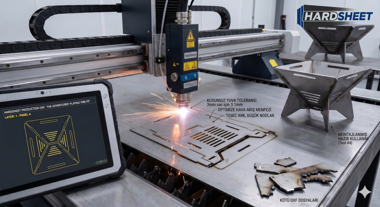
At Hardsheet, we design production-ready DXF blueprints that respect the mechanical limits of both high-end lasers and heavy-duty plasma tables. Our files feature optimized arc paths, calculated node reduction, and plasma-friendly corner profiles that eliminate torch hesitation.
Load our files, dial in your feed rate, and enjoy clean, ready-to-ship parts straight off the cutting bed.




I do not even know how I ended up here, but I thought this put up was once great. I do not realize who you might be but certainly you’re going to a famous blogger if you are not already 😉 Cheers!