How to Optimize Fiber Laser Cutting Parameters for Flawless CNC Sheet Metal Production

Fiber laser cutting machines have revolutionized the sheet metal fabrication industry. They offer incredible speed, extreme precision, and lower operating costs compared to old CO2 lasers or plasma cutters.
However, owning a high-tech fiber laser is only half the battle. To get a clean, dross-free cut without wasting expensive assist gases or damaging your laser head, you must master the relationship between your machine parameters and the DXF file geometry.
In this guide, we will break down the essential fiber laser settings you need to optimize for high-quality production.
1. Choosing the Right Assist Gas: Oxygen vs. Nitrogen
The choice of assist gas changes everything—from your cutting speed to the post-processing time required for your parts.
-
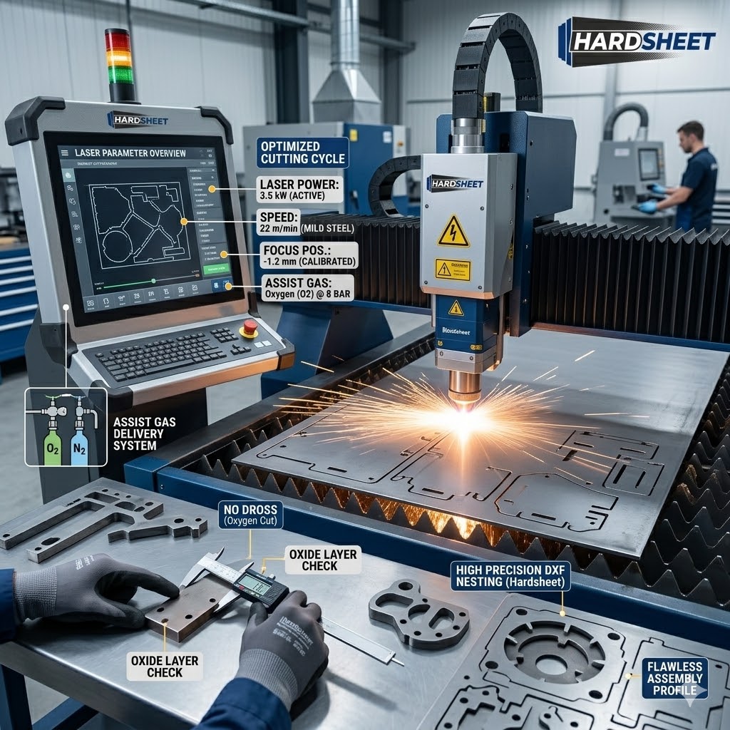
Oxygen ($O_2$): Typically used for carbon steel (mild steel). Oxygen creates a chemical reaction (burning) that helps melt the metal, allowing lower-power lasers to cut thicker plates. However, it leaves an oxide layer on the cut edge that must be ground off before painting or powder coating.
-
Nitrogen ($N_2$): Used for stainless steel, aluminum, and thin mild steel. Nitrogen purely uses mechanical pressure to blow away the molten metal without oxidation. It results in a shiny, ready-to-weld edge, but requires much higher pressure and laser power.
2. Laser Focal Position (Focus Height)
The focal spot is the point where the laser beam is at its highest concentration. Getting the focus height wrong is the number one cause of heavy dross (burr) and rough cut edges.
-
Thin Sheets: For thin materials, the focus point is usually set right on the top surface or slightly inside the material ($0$ to negative focus).
-
Thicker Plates: When cutting thick mild steel with Oxygen, the focus is often raised above the sheet (positive focus) to create a wider kerf, allowing the gas to enter the cut cleanly and blow out the molten metal.
3. Cutting Speed vs. Laser Power Balance
Running your fiber laser at maximum speed sounds efficient, but if the speed outpaces the laser power, the beam won’t fully penetrate the sheet. This causes “back-reflection,” which can ruin your protective windows or even damage the laser ceramic and nozzle.
Conversely, moving too slowly dumps excessive heat into the sheet metal. For intricate DXF files with fine details, slow speeds cause the corners to melt away—a phenomenon known as “over-burning.”
4. Nozzle Selection and Centering
Your nozzle dictates the flow shape of the assist gas. If the laser beam is not perfectly centered inside the nozzle opening, the gas flow will be asymmetrical.
-
The Symptom: Your machine will cut beautifully when moving left-to-right, but leave heavy dross or fail to cut entirely when moving right-to-left.
-
The Routine: Always perform a “tape shot” test to verify perfect nozzle centering before starting a long production run.
Conclusion: Engineered DXF Files Mean Flawless Fiber Cutting
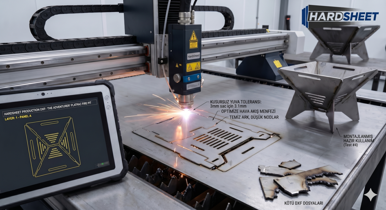
Even with a perfectly calibrated 12kW fiber laser machine, you cannot get a premium product from a poorly optimized vector file. If a DXF design has overlapping lines, loose nodes, or micro-gaps, your laser head will stutter, lose its height regulation (capacitive sensing), and potentially crash into the sheet.
At Hardsheet, we engineer our DXF files specifically with high-speed CNC fiber laser capabilities in mind. Our drawings feature smooth arcs, closed loops, and calculated nesting layouts that let your laser head glide effortlessly at maximum speed.
Optimize your files, save your nozzles, and boost your workshop’s daily output.