The Ultimate Engineering Guide to Sheet Metal Bending: K-Factor, Bend Allowance, and Press Brake Calculations


In the world of precision CNC sheet metal fabrication, transitioning a beautifully modeled 3D assembly into a flawless 2D DXF cutting flat pattern is one of the most challenging tasks. If you have ever loaded an engineered drawing into your fiber laser or plasma cutter, bent it on a press brake, and discovered that the final dimensions were off by $1.5\text{mm}$ or $2.0\text{mm}$, you have experienced the consequences of incorrect bending calculations.
Many hobbyists and amateur designers mistakenly believe that a flat pattern is simply the sum of the physical flanges. However, metal behaves like a dynamic fluid under extreme mechanical pressure. When a sheet is bent, it stretches on the outside and compresses on the inside.
To achieve high-precision results for interlocking slots, tabs, and industrial brackets, you must master the physics of sheet metal deformation. This comprehensive guide will break down the mathematics behind the K-Factor, Bend Allowance, and Bend Deduction, ensuring your production runs achieve zero-waste efficiency.
1. The Physics of Deformation: Understanding the Neutral Axis
To understand why flat patterns cannot be calculated by simply adding nominal flange lengths, we must look at what happens inside the grain profile of the steel sheet during a press brake stroke.
When a sheet of steel, aluminum, or stainless steel is forced into a V-die, the material undergoes a dual stress cycle:
-
The Inside Zone: The surface facing the punching tool is heavily compressed. The material molecules are forced together, causing a slight thickening near the bend radius.
-
The Outside Zone: The surface facing the V-die is subjected to high tensile stress. The material stretches, leading to thinning along the outer corner.
-
The Neutral Axis: Located somewhere between these two opposing forces is a theoretical plane where the material experiences zero stress—it neither stretches nor compresses.
The length of this neutral axis is the exact structural length your flat 2D DXF vector layout needs to be. The primary objective of all sheet metal calculations is to pinpoint the shifting location of this neutral axis.
2. Demystifying the K-Factor: The Critical Ratio
The K-Factor is not a fixed mathematical constant; it is a dynamic ratio that defines the displacement of the neutral axis during a physical bend.
Formally, the K-Factor is calculated using the following equation:
$$K = \frac{t}{T}$$
Where:
-
$t$ = The distance from the inside surface of the bend to the neutral axis.
-
$T$ = The total nominal material thickness.
Plaintext
       ◀───── Total Material Thickness (T) ─────▶
      ┌──────────────────────────────────────────┐
      │          COMPRESSION ZONE                │
      ├ - - - - - - - - - - - - - - - - - - - - -┤ ◄─── Neutral Axis (t)
      │          STRETCHING ZONE                 │
      └──────────────────────────────────────────┘
When sheet metal is perfectly flat, the neutral axis sits exactly in the middle of the sheet profile ($K = 0.50$). However, the moment the press brake upper tool contacts the metal and forces it into the die, the material on the outside yields and stretches much faster than the inside compresses. As a direct result, the neutral axis shifts inward toward the inside bend radius.
In standard commercial air bending setups, the K-Factor typically ranges between $0.30$ and $0.50$.
Factors that Dynamically Alter the K-Factor:
-
Material Ductility: Softer metals like aluminum stretch easier, pulling the neutral axis further inward (lower K-Factor), whereas high-tensile stainless steel resists stretching (higher K-Factor).
-
Bending Method: Coin bending or bottoming physically crushes the inner radius, resulting in entirely different material displacement ratios than standard CNC air bending.
-
Ratio of Bend Radius to Thickness ($R/T$): When your inside bend radius is smaller than the material thickness, the material experiences severe stress, causing the K-Factor to drop toward $0.33$. If the radius is exceptionally wide, the K-Factor climbs back toward $0.50$.
3. Calculating the Geometry: Bend Allowance vs. Bend Deduction
To accurately unfold a 3D CAD model into a production-ready 2D vector graphic, engineers utilize two primary geometric metrics: Bend Allowance (BA) and Bend Deduction (BD).
Plaintext
                  ◄─── Flange 1 (L1) ───►
                 ┌──────────────────────┐
                 │                      │
                 │                      └───────┐ ┐
                 │       BEND ZONE              │ │ Flange 2
                 │      (Allowance)             │ │  (L2)
                 │                      ┌───────┘ ┘
                 │                      │
                 └──────────────────────┘
Bend Allowance (BA)
Bend Allowance represents the exact arc length of the neutral axis within the deformed bend zone. It is the amount of physical material wrapped around the radius. The universal mathematical formula for Bend Allowance, incorporating the K-Factor, is expressed as follows:
$$BA = A \cdot \frac{\pi}{180} \cdot \left(R + K \cdot T\right)$$
Where:
-
$BA$ = Bend Allowance
-
$A$ = The bend angle in degrees (e.g., $90^\circ$)
-
$R$ = The inside bend radius
-
$T$ = Total material thickness
-
$K$ = K-Factor
By executing this calculation, you determine exactly how much flat sheet metal is consumed by the corner radius itself.
Bend Deduction (BD)
While Bend Allowance calculates the neutral axis arc directly, press brake operators usually measure parts by their Outside Mold Lines (OML)—the theoretical sharp intersection points of the outside flanges.
Bend Deduction is the value subtracted from the total sum of the outside flange lengths to compensate for material stretching:
$$Flat\ Pattern\ Length = L_1 + L_2 – BD$$
To calculate Bend Deduction mathematically, you must first calculate the Outside Set Back (OSB), which represents the distance from the tangent point of the bend to the sharp outside intersection apex:
$$OSB = \tan\left(\frac{A}{2}\right) \cdot (R + T)$$
Once the Outside Set Back is established, Bend Deduction is derived using the following relation:
$$BD = 2 \cdot OSB – BA$$
By substituting these calculations directly into your vector nesting layouts, your flat DXF parts will line up perfectly with zero clearance errors post-bending.
4. Industry Standard Parameter Charts for CAD Settings
When configuring sheet metal parameters inside 3D modeling environments like SolidWorks or Autodesk Inventor, relying on default software settings will lead to structural errors on the shop floor.
Below is an engineering reference table outlining the standard K-Factor parameters applied in high-precision CNC air bending operations using matching V-die widths ($V = 6 \cdot T$ to $8 \cdot T$):
| Material Type | Thickness Range (mm) | Inside Bend Radius (mm) | Recommended K-Factor |
| Mild Steel (CR / HR) | $0.5\text{mm} – 1.5\text{mm}$ | Equal to Thickness | $0.42$ |
| Mild Steel (CR / HR) | $2.0\text{mm} – 4.0\text{mm}$ | Equal to Thickness | $0.44$ |
| Stainless Steel (304/316) | $1.0\text{mm} – 3.0\text{mm}$ | $1.2 \times$ Thickness | $0.38$ |
| Aluminum (5052-H32) | $1.0\text{mm} – 2.5\text{mm}$ | Equal to Thickness | $0.40$ |
| Aluminum (6061-T6) | $2.0\text{mm} – 4.0\text{mm}$ | $2.0 \times$ Thickness | $0.45$ |
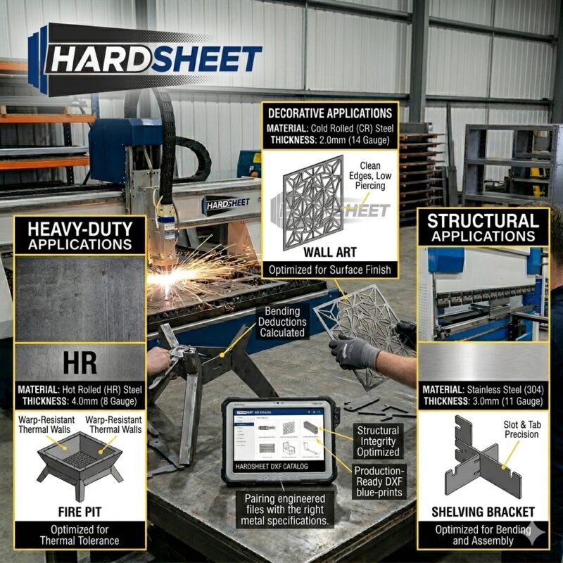
⚠️ Pro Engineering Note: When working with specialized structural components or air-pack heavy assemblies (like heavy-duty wood stoves or structural brackets), always run a physical test strip ($100\text{mm}$ sample cut) on your specific press brake to reverse-engineer the exact K-factor of your tooling array before initiating bulk production.
5. Designing for the Press Brake: Crucial Rules for DXF Layouts
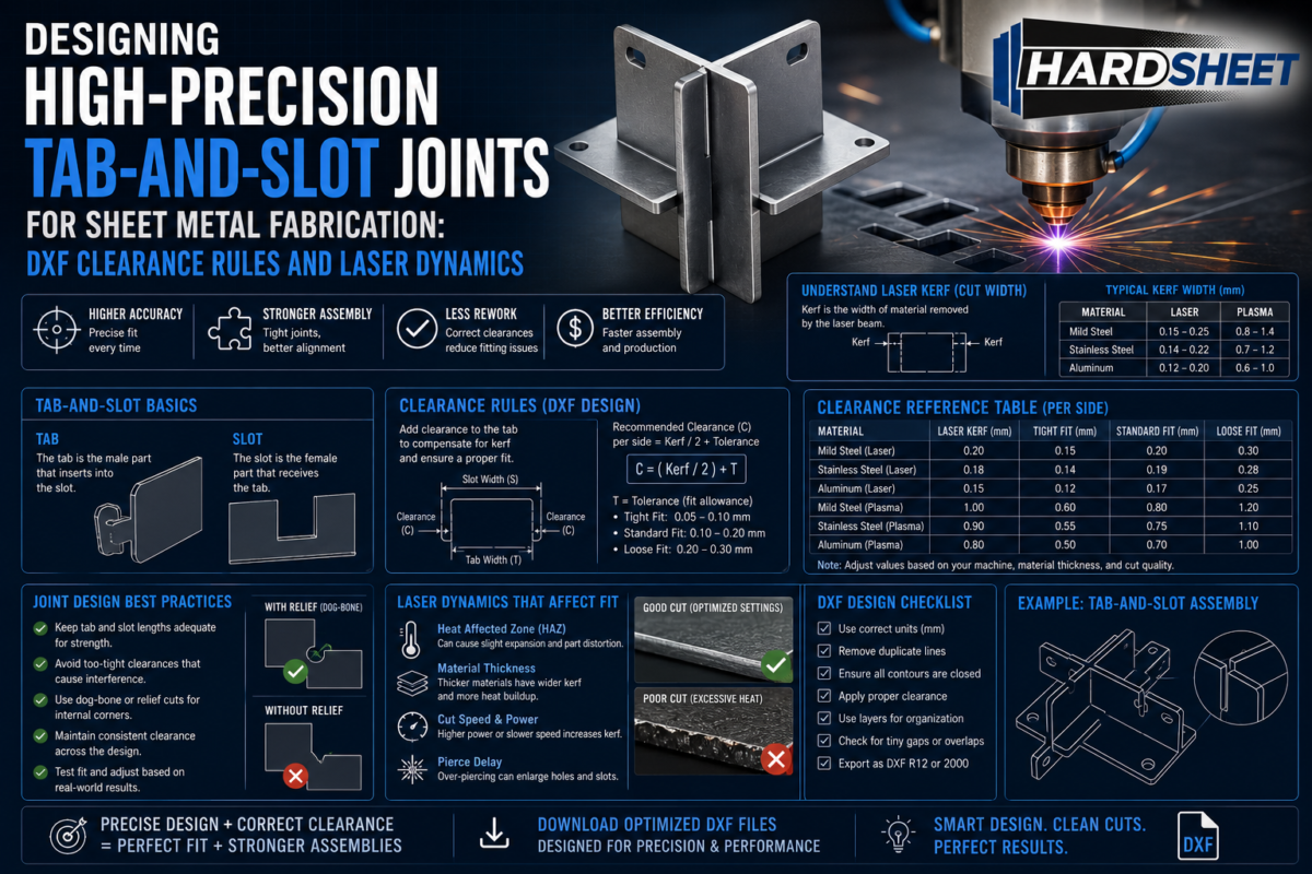
An engineered DXF file is far more than a clean vector profile; it must actively anticipate the mechanical physical limitations of the press brake machinery. When drawing your sheet metal components, always adhere to these four critical rules:
Rule 1: Minimum Flange Height
If a flange layout is designed too short, it will fail to bridge the opening of the V-die during the press stroke. The sheet will slip inside the die cavity, causing severe geometric distortion and risking tool damage.
-
The Rule: The absolute minimum inside flange height ($H_{\text{min}}$) must follow this calculation:
$$H_{\text{min}} = 4 \cdot T + R$$
Rule 2: Relief Cut Sizing
When a bend terminates inside the boundary edge of a sheet metal plate rather than spanning across the full width, the material will tear unevenly due to tearing stresses.
-
The Rule: Always place a dedicated bend relief cut at the intersection. The width of the relief cut must be at least equal to the material thickness ($T$), and its depth must extend beyond the tangent point of the bend radius.
Rule 3: Hole Proximity to Bends
Placing structural fastening holes or decorative geometric cutouts too close to a bend line will cause severe elongation. As the metal stretches along the outer mold zone, circular holes will deform into ugly, non-functional ovals.
-
The Rule: Keep the edge of any cutout or hole a minimum distance away from the bend line:
$$Distance_{\text{min}} = 3 \cdot T + R$$
Conclusion: The Hardsheet Commitment to Precision Engineering
In modern manufacturing, speed and accuracy are the two metrics that dictate profitability. If your workshop wastes hours manually correcting flat patterns or grinding parts to fit together because of miscalculated bend tolerances, your operational overhead will soar.
At Hardsheet, we treat technical draughting as an exact science. We don’t supply generic vector lines that look pretty on a monitor but fail on the shop floor. Every DXF listing in our catalog is engineered by a professional technical draughtsman with a profound understanding of K-factor mechanics, material grain direction, and press brake bending deductions.
Our files feature calculated bend clearances, optimized relief paths, and perfect slot-and-tab tolerances. When you download a blueprint from Hardsheet, you are launching a product designed for efficient, zero-waste manufacturing.
Maximize your machinery capabilities, protect your consumables, and streamline your production lines.
👉 [Access Our Catalog of Production-Ready Precision DXF Blueprints]